O/D Spares
Technical & Troubleshooting
| |||||
| |||||
| |||||
| |||||
| |||||
|
HOW AN OVERDRIVE WORKS
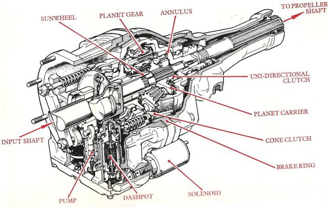
The cone clutch is moved forward by hydraulic pressure in the operating cylinders, so that the outer friction lining of the clutch comes into contact with the stationary brake ring. As the cone clutch is attached to the sunwheel, both come to rest and the sunwheel becomes the reaction member for the planetary train. Since the planet carrier is splined to the input shaft and driven by it, the planet wheels orbit round the stationary sunwheel and in so doing, rotate the annulus and output shaft at a speed greater than that of the carrier and input shaft. The UDC enables the output member to rotate faster than the input member.The forward drive is transmitted directly through the uni-directional clutch (UDC). The cone clutch is held rearwards by spring pressure exerted through a thrust ring and ball race, loading the inner friction lining of the clutch in contact with the outside diameter of the annulus on the output shaft (the loading is further increased by the reverse thrust of the helical sunwheel). Thus the gear train is locked and overrun or reverse torque is taken by the cone clutch, without which, the UDC would give a freewheeling condition.
The overdrive is operated by an electric solenoid controlled by a switch, usually mounted on the steering column or fascia panel. An inhibitor switch is invariably fitted in the electrical circuit to prevent engagement of overdrive in reverse and some or all of the indirect gears.
The overdrive gears are epicyclic (planetary) and consist of a sunwheel, three planet gears and an internally toothed ring gear or annulus. All gears are in constant mesh. The planet carrier is attached to the input shaft. Carried on an extension of the sunwheel, a double sided cone clutch engages with a stationary brake ring or with the outside surface of the annulus. A uni-directional clutch (UDC) or freewheel connects the input and output shafts.
Oil is drawn from the sump through the suction filter by the reciprocating pump and delivered to the pressure filter. It then passes through to the relief valve and acts upon the solenoid valve which is closed. Oil passes through the relief valve spill port and is conducted into the main drive shaft to lubricate the running gear. Excessive pressure build up in the lubrication pasages is prevented by the lube relief valve which operates at a predetermined pressure.
Since oil supply to the dashpot is withheld by the solenoid valve, the dashpot piston is held down by its spring(s). Movement of the relief valve piston is resisted by the spring, the strength of which determines the residual pressure within the system when the unit is in direct drive. It is necessary to maintain this residual pressure in order to initiate action of the system when engagement is signalled and for lubrication.
When the solenoid is energised, its valve opens and oil - at residual pressure - is allowed to enter the passage which leads to the dashpot. An increase in system pressure results from the "out-of-balance" between the dashpot piston and the relief valve piston due to their differing areas. This causes the dashpot assembly to compress the residual spring. The dashpot then continues to move compressing the dashpot spring until the dashpot piston contacts the dashpot cup.
The reaction of the increasing load of the relief valve spring being applied to the relief valve piston, progressively increases the system pressure. The dashpot piston continues to its stop by which time the relief valve spring has been compressed to its working length, thus giving full system pressure.
When the solenoid is de-energised its valve is returned by a spring allowing oil to exhaust from the dashpot. The relief valve spring is able to gradually relax towards its direct drive position. Progressively, the system pressure will drop and eventually allow the cone clutch to leave the brake ring and move gently into contact with the annulus. The supplementary dashpot spring provides additional load upon the piston and allows relative rotation between the cone clutch and the brake ring as the engine speed rises and the UDC takes up direct drive.
Smooth overrun disengagements are obtained by progressively increasing the load on the inner clutch linings, compared with that provided by the free action of the clutch springs by varying the hydraulic pressure which off-sets the clutch spring load and determines the net loading at the clutch face. This is accomplished by controlling the diminution of pressure determined by the action of the dashpot piston, exhausting oil through the discharge orifice. When the contents of the dashpot have been fully discharged, the system pressure has fallen to its original residual value.

TROUBLESHOOTING GUIDE
Low oil level
No electrical feed to solenoid
Solenoid valve sticking due to dirt
Blocked oil flters
Dirt in pump non-return valve
Sticking relief valve piston
If these items check out OK, engage the clutch fiercely with overdrive switched in on the overrun in third gear at 40/45mph.
Failure to Disengage
Check electrical system for 'closed circuit'
Remove solenoid and check for seized plunger
Check relief valve for sticking components
Check relief orifice for blockage
Check for sticking clutch by giving brake ring several taps with a hide mallet.
|
8th July 2025
|
Tel: 01788 540666 |
||
|
|
|||
